Friday, April 17, 2015

HW Config: Edit Symbolic Names, Monitor/Modify Variables


HW Config Edit Symbolic Names  Monitor Modify Variables
Edit Symbolic Names
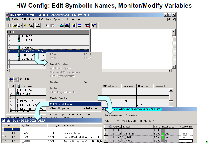
You can directly access the symbol table from the "HW Config" tool. This allows
you to assign symbolic names to the inputs and outputs during hardware
configuration or at a later date when you can make suppliments or changes.
You open the symbol table with a right mouse click on the module. Select Edit
Symbolic Names in the follow-up box. A section of the symbol table with the
relevant addresses is then opened.

Monitor/Modify Variables
You can monitor or modify the addresses of the configured modules directly from the HW Config tool. The signals of the input modules can be "checked" and
the signals of the output modules can be "controlled" using the Monitor/Modify
(Variables) function.

Product Support Information
Directly from the Internet, you can fetch information on modules or components from the Product Support pages. As well, it is also possible to update HW Config
by incorporating individual components such as new CPUs or new DP devices
into the current STEP 7 version.
Requirements:
The PG/PC has an Internet connection, a browser for displaying Internet pages,
and the function is enabled in the HW Config Settings along with the
specification of the Internet address.

Note
"Symbolic Addressing" and the editing of symbol tables is dealt with in depth in
the "Symbols" chapter. The Monitor / Modify Variables function is dealt with in
the "Troubleshooting" chapter.

CPU Propertires: Cycle  / Clock Memory

CPU Propertires Cycle  Clock Memory

Cycle
• "Scan cycle monitoring time (ms):"
- If this time is exceeded, the CPU goes into the STOP mode.
   Possible causes why this time is exceeded: communications processes,
   frequently from interrupt events, errors in the CPU program.
- If you have programmed an error OB 80, the scan cycle time is doubled.
  After that, the CPU also goes into the STOP mode.
• "Cycle load from communication (%):"
- Communication (such as data transmission to another CPU through MPI
  or test functions the PG/PC triggered) is restricted to the specified
  percentage of the current scan cycle time.
- Restricting the cycle load can slow down communication between the
  CPU and PG.
- Example: Restricting communication to 20% results in a maximum
  communication load of 20ms for a scan cycle time of 100ms.
Size of the  Process Image 
With the CPU 318-2 and several S7-400  CPUs, you can specify the size of the process image (in bytes). The process image area always begins with input
and output byte 0.

clock memories pulse


Saving the HW Setpoint Configuration and Downloading it in Module

Saving the HW Setpoint Configuration and Downloading it in Module

Save
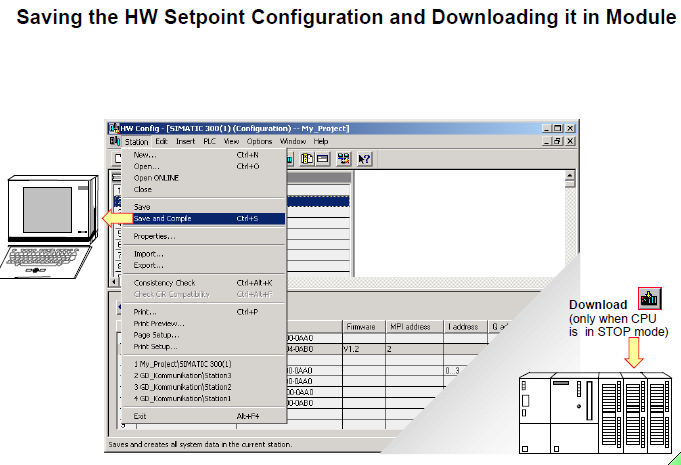
You select the Station->Save menu to save the current configuration in the
current project (without generating system data blocks).

Save and Compile
When you select the Station->Save and Compile menu or click the
icon  on the toolbar, the configuration and parameter assignment data are
also saved in system data blocks.

Consistency Check
You select the Station -> Consistency Check menu to check whether it is
possible to generate configuration data from the entries made.

Download in Module
You select the PLC -> Download menu or click the icon in the toolbar to
download the selected configuration to the PLC.
The PLC must be in "STOP" mode!

System Data Blocks
The system data blocks (SDBs) are generated and modified when you configure
the hardware and compile the hardware configuration. SDBs contain
configuration data and module parameters. When a system data block is
downloaded, it is stored in the CPU‘s work memory.
This makes it easier to replace modules, because the parameter assignment
data is downloaded to the new module from the system data blocks on startup.
In the programming device, the system data blocks are saved under: Project \
Station \ CPU \ S7_program \ Blocks \ System_data.
You double-click the System data briefcase icon to see the list of system
data blocks.
If you use a memory card as Flash EPROM, you should save the SDBs there as
well. That way, the configuration is not lost if you operate without battery backup
and there is a power failure.


Upload Actual Configuration to the PG/PC and Rename It

Upload Actual Configuration to the PG/PC and Rename It

Task
To upload a PLC‘s hardware configuration. Since the project called "My_Project"
does not yet have a HW Station, you are to read out the actual PLC
configuration from your training area. Rename the newly created hardware
station in the project "My_Station".

What To Do
• Start the SIMATIC  Manager and open your project called "My_Project"
• Load the actual configuration from your training area into your project;
in SIMATIC  Manager -> highlight My_Project -> PLC menu -> Upload
Station -> OK
Complete the follow-up dialog box as shown in the slide above. If no
"Accessible Nodes" are visible, you must click "Update".
• Rename the newly created "SIMATIC  300(1)" hardware station
"My_Station"
Click twice on "SIMATIC  300(1)" (not a double-click !) and type
"My_Station"

Result
In your project called "My_Project" you now have a hardware station called
"My_Station" and the hardware-independent program called "My_Program" (see
bottom picture of slide).


Adapting the ACTUAL Configuration

Adapting the ACTUAL Configuration

Task
The ACTUAL configuration read out with "Upload Station" is incomplete
because several module order numbers are missing. These numbers are
necessary to clearly identify and assign parameters to the modules. You are to
enter the order numbers of the modules of your training area (located on the
bottom, outside module cover) in the uploaded "actual configuration".

What To Do
1. Start the HW Config tool
SIMATIC  Manager (Offline view) -> select HW Station called "My_Station"
-> double-click "Hardware" icon
2. Update the modules with correct order numbers
double-click each signal module -> in the dialog box "Specify Module",
choose the correct part number for the modules on your training area ->
confirm the follow-up "Properties" dialog box with OK (since the preset
standard parameters do not have to be changed).
3. Only if your training unit is an S7-400:
Specify the module addresses so that they correspond to those of an
S7-300 training unit with 32 channel modules (see slide)
double-click on Module -> specify the address in the Properties dialog box
4. Save and compile the adapted ACTUAL configuration
Station -> Save and Compile
5. Download the adapted ACTUAL configuration to the CPU
PLC -> Download
6. Exit the HW Config tool

Result
The hardware station called "My_Station" in your project called "My_Project"
corresponds to the main rack of your training unit.


Tuesday, March 24, 2015

Addressing S7-300 Modules

Addressing S7-300 Modules

Slot Numbers
The slot numbers in the rack of an S7-300 simplify addressing in the
S7-300  environment. The position of the module in the rack determine the first
address on a module.

Slot 1
Power supply. This is the first slot by default.
A power supply module is not absolutely essential. An S7-300  can also be
supplied with 24V directly.

Slot 2
Slot for the CPU.

Slot 3
Logically reserved for an interface module (IM) for multi-tier configurations using
expansion racks. Even if no IM is installed, it must be included for addressing
purposes.
You can physically reserve the slot (such as for installing an IM at a later date) if
you insert a DM370 dummy module.

Slots 4-11
Slot 4 is the first slot that can be used for I/O modules, communications
processors (CP) or function modules (FM).
Addressing examples:
• A DI module in slot 4 begins with the byte address 0 .
• The top LED of a DO module in slot 6 is called Q8.0 .

Note
Four byte addresses are reserved for each slot. When 16-channel DI/DO
modules are used, two byte addresses are lost in every slot!

DI/DO Addressing in Multi-Tier Configurations

Multi-Tier Configurations
The slots also have fixed addresses in a multi-tier configuration.

Examples:
• Q7.7 is the last bit of a 32-channel DO module plugged into slot 5 of rack 0.
• IB105 is the second byte of a DI module in slot 6 of rack 3.
• QW60 is the first two bytes of a DO module in slot 11 of rack 1.
• ID80 is all four bytes of a 32-channel DI module in slot 8 in rack 2.


Module Address Overview

Address  Overview
Views the I/O addresses of the station configured. Select: View -> Address Overview …

Abbreviations:
R Rack number
S Slot number of the relevant module
DPRelevant only when Distributed Peripherals (I/O) are used
IF Interface module ID when programming the M7 system (in C++).

Variable Addressing

Slot dependent Addressing 
The modules are assigned fixed slot-dependent addresses with the S7-300  (CPUs without DP interface) and S7-400 (without hardware configuration).

Variable Addressing
With the S7-300  (CPUs with integrated DP interface) and with the S7-400 you can assign parameters to the starting addresses of the modules.

What to Do
When you double-click a digital or an analog module, the parameter assignment
screen is opened. After you choose the "Addresses" tab, you can cancel
"System selection". You can now define the starting address in the "Start" box. If
the address is already used, an error message is triggered.
Part process images can be defined only in the S7-400 . That way, specific
inputs and outputs (such as time-critical signals) can be combined into one
group. A system function triggers the updating of a part process image in the
user program.

Note
After a CPU memory reset, the parameters, and therefore also the addresses
are lost. This means that the slot-dependent addresses of the S7-300  or the
default addresses of the S7-400  are valid once more.


Friday, March 13, 2015

Hardware Configuration and Parameter Assignment


HW Configuration
The modules are supplied from the factory with preset parameters. If these
default settings are OK, a hardware configuration is not necessary.
A configuration is necessary:
• if you want to modify preset parameters or addresses of a module (such as
to enable the hardware interrupt of a module)
• if you want to configure communication connections
• with stations that have distributed peripherals (PROFIBUS-DP)
• with S7-400  stations that have several CPUs (multicomputing) or
expansion racks
• with fault-tolerant programmable logic controllers (option package).

Setpoint Configuration 
When you configure a system, a setpoint configuration is created. It contains a hardware station with the planned modules and the associated parameters. The
PLC system is assembled according to the setpoint configuration. During
commissioning, the setpoint configuration is downloaded to the CPU.

Actual Configuration
In an assembled system, the actual existing configuration and parameter
assignment of the modules can be uploaded from the CPU. This creates a new
HW station in the project.
A configuration upload is necessary, for example, if the project structure does
not exist locally at the PG. After the actual configuration is read out, you can set
parameters and add part numbers.

Notes
With the S7-400, the CPU can be assigned parameters in such a way, that
when there are differences between the setpoint configuration and the actual
configuration, the CPU startup is interrupted.
To call the HW Config tool, there must be a hardware station in the SIMATIC
Manager.


Starting the HW Configuration Editor

HW Config
This tool helps you configure, assign parameters to and diagnose the hardware.

Starting HW Config
To start the HW Config tool:
• select a hardware station in the SIMATIC Manager and choose the Edit --> Open Object menu or
• double-click the hardware object.

"Hardware Configuration"
This is a window in the "HW Config“ application you use for inserting components from the "Hardware Catalog" window.
The title bar of this window contains the name of the project and the station
name.

"Hardware Catalog"
To open the catalog:
• select the View -> Catalog menu or
• click the icon in the toolbar.
If “Standard” is selected as the catalog profile, all racks, modules and interface
modules are available in the "Hardware Catalog" window.
You can create your own catalog profiles containing frequently used elements
by selecting the menu options Options -> Edit Catalog Profiles.
You can add Profibus Slaves that do not exist in the catalog later on. To add
slaves, you use GSE files that are provided by the manufacturer of the slave
device. The GSE file contains a description of the device. To include the slave in
the hardware catalog, use the Options -> Install New GSE Files menu and then
Options -> Update Catalog. You will find the new devices in the catalog under
Profibus, additional field devices.


Generating a Hardware Setpoint Configuration

Generating a Setpoint  Configuration
This means specifying how the modules are to be arranged in the rack. This configuration, specified by you, is referred to as the setpoint configuration.

Rack
For example, you open a SIMATIC  300 station in the Hardware Catalog.
Opening the "RACK-300" folder shows the icon for a DIN rail. You can insert this
in the "Hardware Configuration" window by double-clicking on it (or using drag &
drop).
Two rack component lists then appear in the two-part window: a plain list in the
top part and a detailed view with order numbers, MPI addresses and I/O
addresses in the bottom part.

Power Supply
If a load current power supply is required double click or use drag & drop to
insert the appropriate "PS-300" module from the catalog in slot no.1 in the list.

CPU
You select the CPU from the "CPU-300" folder, for example, and insert it in slot
no. 2.

Slot No. 3
Slot no. 3 is reserved as the logical address for an interface module (for multitier
configurations).
If this position is to be reserved in the actual configuration for the later
installation of an IM, you must insert a dummy module DM370 (DUMMY).

"Inserting" Modules
From slot no. 4 onwards, you can insert a choice of up to 8 signal modules
(SM), communications processors (CP) or function modules (FM) from the
HardwareCatalog using drag & drop or with a double-click.
The slots on which the selected module can be inserted are automatically
highlighted in green.


Friday, March 6, 2015

Copying a Block from the Standard Library


Task
For later use, copy the FC105 block from the STEP7 "Standard Library" into the
Blocks folder of the Step7 Program "My_Program" in the project "My_Project".

What To Do
1. Open the "Standard Library" in the SIMATIC Manager:
File > Open... -> select the "Libraries" tab -> choose "Standard Library" in the
list -> confirm
2. In the project "Standard Library" open the Blocks folder of the S7 Program
"TI-S7-Converting Blocks"
3. Display your project called "My_Project" and the "Standard Library" at the
same time in two windows in the SIMATIC  Manager
Window > Arrange > Horizontally
4. Using drag & drop, copy the FC 105 block from the "Standard Library" into
your program folder "My_Program"
5. Close the library.

Result
The FC 105 block is stored in the Blocks folder of your Step7 Program called
"My_Program" in addition to the still empty OB 1.

Notes
Libraries are used for storing blocks which contain standardized functions. You
can copy the blocks from the library into any project you wish. If the name
(number) of the block you are copying already exists, you can rename the library
block (number) when you insert the block into your program folder.

Performing a CPU Memory Reset and Warm Restart

Task
You are to perform a CPU memory reset and check whether the memory reset
was successful.

What To Do
• Carry out the memory reset according to the steps in the slide above
• Check the success of the memory reset. The memory reset was successful
when only system blocks (SDBs, SFCs, SFBs) are left in the CPU
in the SIMATIC Manager, select the Step7 Program folder "My_Program" ->
switch to the Online view.

Notes
When the CPU memory is reset, all user data in the CPU are deleted.
To make sure that no “old” blocks are left in the CPU, a memory reset of the
CPU should be performed. The following takes place during a memory reset:
• All user data are deleted
(with the exception of the MPI parameter assignments).
• Hardware test and initialization
• If an Eprom memory card is installed, the CPU copies the EPROM contents
back into the internal RAM after the memory reset.
• If no memory card is installed, the preset MPI address is retained. If,
however, a memory card is installed, the MPI address stored on it is loaded.
• The contents of the diagnostic buffer (which can be displayed with the PG)
are retained.


Tuesday, March 3, 2015

Offline / Online View in the SIMATIC Manager


Offline View
In the project window of the SIMATIC  Manager, the offline view displays the
project structure stored on the hard disk of the programming device.
The " Step7 Program" folder contains the "Sources" and "Blocks" objects.
The "Blocks" folder contains the system data created with the HWConfig tool
and the blocks created with the LAD/STL/FBD Editor.

Online View
The online view shows the offline project structure in the left window and in the
right window it shows the blocks stored online in the selected CPU.
As a result, the " Step7 Program" seen in the online view only contains the "Blocks"
folder which contains the following objects:
• System data blocks (SDB)
• User blocks (OB, FC, FB)
• System blocks (SFC, SFB).

Changing Views
Changing between offline and online view takes place:
• through the View -> Offline or View -> Online menu items
or
• with the corresponding symbol in the toolbar:

Online
Offline

Note
You can arrange the "ONLINE" and "OFFLINE" views next to each other or
under each other when you use the Window -> Arrange option in the menu bar.


Standard Library

Introduction
Libraries are used to store reusable blocks.The blocks can be copied into a
library from existing projects or they can be created directly in the library
independent of projects.

Standard Library
A Standard Library is installed when you install STEP 7. You can access this standard library from the SIMATIC  Manager (File -> Open -> Libraries) or from
the Block Editor (Overviews -> Libraries). The library contains the following S7
programs:

Communication Blocks:
FCs (functions) for communication between the CPU and the distributed I/O
via communication processors.

Organization Blocks: Organization blocks (OBs).

S5-S7 Converting Blocks:
Blocks that emulate STEP 5 standard function blocks and that are necessary for converting STEP 5 programs.

TI - Step7 Converting Blocks: Generally usable standard functions such as analog value scaling.

IEC Function Blocks:
Blocks for IEC functions (IEC: International Electrotechnical Commission), such
as for processing time and date information, for string processing and for
selecting maximum and minimum.

PID Control Blocks: Function blocks (FBs) for PID closed-loop controls.

System Function Blocks: System functions (SFCs) and System function blocks (SFBs).

Miscellaneous Blocks: 
FCs and Fs for switching between daylight savings time and and standard time
(summer and winter times).

Note Additional libraries are added when optional software is installed.


Thursday, February 26, 2015

The Step7 Simatic Manager


Process
When you take a closer look at a process you want to automate, you will find
that it is made up of a multitude of smaller sections and sub-processes, which
are all interlinked and dependent on one another.
The first task is therefore to break down the automation process as a whole into
separate sub-tasks.

Hardware and Software
Each sub-task defines certain hardware and software requirements which the the automation system must fulfill:
• Hardware:
- Number and type of inputs and outputs
- Number and type of modules
- Number of racks
- Capacity and type of CPU
- HMI systems
- Networking systems
• Software:
- Program structure
- Data management for the automation process
- Configuration data
- Communication data
- Program and project documentation.

Project
In SIMATIC STEP7 all the hardware and software requirements of an automation
process are managed within a project.
A project includes the necessary hardware (+ configuration), network
(+ configuration), all the programs, and the entire data management for an
automation solution.

Imatic Step7 Project Structure

Multiproject
The multiproject folder is the folder for all projects and libraries of an automation
solution that contains one or more STEP7 projects and optionally, also libraries.
That way, the complete solution can be divided into individual, easy to follow
projects. The projects within the multiproject can contain objects with crossproject
interrelations (such as cross-project Step7 connections).

Project Structure
Data is stored in a project in the form of objects. The objects in a project are
arranged in a tree structure (project hierarchy). The tree structure displayed in
the project window is similar to that in the Windows Explorer. Only the icons for
the objects are different.

Project Hierarchy
1st. Level:
The first level contains the project icon. Each project represents a
database where all the relevant project data are stored.
2nd. Level:
• Stations (such as the Step7 - 300™ station) are where information
about the hardware configuration and parameter assignment
data of modules is stored.
Stations are the starting point for configuring the hardware.
• Step7 Program folders are the starting point for writing
programs. All the software for a parameter-assignable
module from the Step7 range is stored in an Step7 Program
folder. This folder contains further folders for the program
blocks and sources.
• Subnets (MPI,Profibus, Industrial Ethernet) are part of an
overall network.
3rd. and subsequent levels: Depends on the object type of the next-higher level.

Sunday, February 22, 2015

Configuration of the Simatic Step7 - 400 Training Unit PS Default Address: CPU DI 32 28 Slot

Design
You can see the design of the Simatic Step7 - 400 training unit in the slide above.

Configuration
The UR 1 mounting rack is configured with the following modules:
Slot 1: Power supply 24V and 5V/20A
Slot 2: - " -
Slot 3: - " -
Slot 4: CPU 412 or other
Slot 5: vacant (when the CPU only has a single width)
Slot 6: vacant
Slot 7: vacant
Slot 8: Digital input 32x24V (from Simulator)
Slot 9: Digital input 32x24V (from Conveyor Model)
Slot 10: Digital output 32x24V 0.5A (to Simulator)
Slot 11: Digital output 32x24V 0.5A (to Conveyor Model)
Slot 12: Analog input 8X13 Bit (from Poti on the Simulator)
Slot 13: vacant
Slot 14: vacant
Slot 15: vacant
Slot 16: vacant
Slot 17: vacant
Slot 18: vacant

Addressing
You have the default addresses, as shown in the slide above, as long as no
configuration or parameter settings have been made.


PLC Simulator

Design
Two cables connect the simulator to the S7-300™ or S7-400™ training unit. The
simulator is divided into the following three sections:
• Binary section with 16 switches/momentary-contact switches and 16 LED's
• Digital section with 4 thumbwheel buttons and a digital display. The
thumbwheel and digital (BCD) display use BCD values,
• Analog section with a voltmeter for displaying the values at analog channels
0 and 1 or the analog outputs 0 and 1. You use the selector switch to choose
the voltage value you want to monitor. There are two separate
potentiometers for setting the values for the analog inputs.

Addressing
You use the following addresses to address the inputs and outputs in your user
program:
Sensor / Actuator
Version A
(DI16, DO16)
Version B
(DI32, DO32)
S7-400
(Default addresses
Switch / M.C.Sw.
IW 0
IW 0
IW 28
LEDs
QW 8
QW 4
QW 36
Thumb. buttons
IW 4
IW 2
IW 30
Digital display
QW 12
QW 6
QW 38
Analog channels
PIW 352/354
PIW 304/306
PIW 1216/1230


The Conveyor Model

Design
The slide shows a diagram of the conveyor model with its sensors and
actuators.

Addresses
S7-300
Ver. A
(DI16,
DO16)
S7-300
Ver. B
(DI32,
DO32)
S7-400
(Default
Ad-
dresses)
Sensor / Actuator
Symbol
I 16.0
I 16.1
I 16.2
I 16.3
I 16.4
I 16.5
I 16.6
I 16.7

Q 20.1
Q 20.2
Q 20.3
Q 20.4
Q 20.6
Q 20.7
I 8.0
I 8.1
I 8.2
I 8.3
I 8.4
I 8.5
I 8.6
I 8.7

Q 8.1
Q 8.2
Q 8.3
Q 8.4
Q 8.6
Q 8.7
I 32.0
I 32.1
I 32.2
I 32.3
I 32.4
I 32.5
I 32.6
I 32.7

Q 40.1
Q 40.2
Q 40.3
Q 40.4
Q 40.6
Q 40.7
Light Barrier at Conv. End
Push Button at Bay1, M.C.
Push Button at Bay2, M.C.
Push Button at Bay3, M.C.
Push Button at End C.MC.
Proximity Sensor at Bay 1
Proximity Sensor at Bay 2
Proximity Sensor at Bay 3

Indicator Light at Bay 1
Indicator Light at Bay 2
Indicator Light at Bay 3
Indicator Light at Conv. End
Run Conveyor Left
Horn
LB
T_PB1
T_PB2
T_PB3
T_PB4
BAY1
BAY2
BAY3

L_BAY1
L_BAY2
L_BAY3
L_END
K_LT
K_Horn