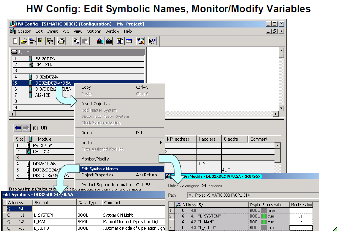
Edit Symbolic Names
You can directly access the symbol table from the "HW Config" tool. This allows
you to assign symbolic names to the inputs and outputs during hardware
configuration or at a later date when you can make suppliments or changes.
You open the symbol table with a right mouse click on the module. Select Edit
Symbolic Names in the follow-up box. A section of the symbol table with the
relevant addresses is then opened.
Monitor/Modify Variables
You can monitor or modify the addresses of the configured modules directly from the HW Config tool. The signals of the input modules can be "checked" and
the signals of the output modules can be "controlled" using the Monitor/Modify
(Variables) function.
Product Support Information
Directly from the Internet, you can fetch information on modules or components from the Product Support pages. As well, it is also possible to update HW Config
by incorporating individual components such as new CPUs or new DP devices
into the current STEP 7 version.
Requirements:
The PG/PC has an Internet connection, a browser for displaying Internet pages,
and the function is enabled in the HW Config Settings along with the
specification of the Internet address.
Note
"Symbolic Addressing" and the editing of symbol tables is dealt with in depth in
the "Symbols" chapter. The Monitor / Modify Variables function is dealt with in
the "Troubleshooting" chapter.
CPU Propertires: Cycle / Clock Memory
Cycle
• "Scan cycle monitoring time (ms):"
- If this time is exceeded, the CPU goes into the STOP mode.
Possible causes why this time is exceeded: communications processes,
frequently from interrupt events, errors in the CPU program.
- If you have programmed an error OB 80, the scan cycle time is doubled.
After that, the CPU also goes into the STOP mode.
• "Cycle load from communication (%):"
- Communication (such as data transmission to another CPU through MPI
or test functions the PG/PC triggered) is restricted to the specified
percentage of the current scan cycle time.
- Restricting the cycle load can slow down communication between the
CPU and PG.
- Example: Restricting communication to 20% results in a maximum
communication load of 20ms for a scan cycle time of 100ms.
Size of the Process Image
With the CPU 318-2 and several S7-400 CPUs, you can specify the size of the process image (in bytes). The process image area always begins with input
and output byte 0.
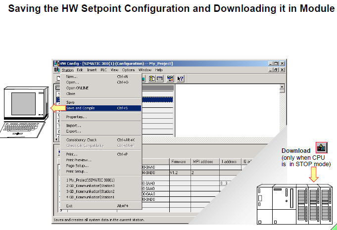
Saving the HW Setpoint Configuration and Downloading it in Module
Save
You select the Station->Save menu to save the current configuration in the
current project (without generating system data blocks).
Save and Compile
When you select the Station->Save and Compile menu or click the
icon on the toolbar, the configuration and parameter assignment data are
also saved in system data blocks.
Consistency Check
You select the Station -> Consistency Check menu to check whether it is
possible to generate configuration data from the entries made.
Download in Module
You select the PLC -> Download menu or click the icon in the toolbar to
download the selected configuration to the PLC.
The PLC must be in "STOP" mode!
System Data Blocks
The system data blocks (SDBs) are generated and modified when you configure
the hardware and compile the hardware configuration. SDBs contain
configuration data and module parameters. When a system data block is
downloaded, it is stored in the CPU‘s work memory.
This makes it easier to replace modules, because the parameter assignment
data is downloaded to the new module from the system data blocks on startup.
In the programming device, the system data blocks are saved under: Project \
Station \ CPU \ S7_program \ Blocks \ System_data.
You double-click the System data briefcase icon to see the list of system
data blocks.
If you use a memory card as Flash EPROM, you should save the SDBs there as
well. That way, the configuration is not lost if you operate without battery backup
and there is a power failure.
Upload Actual Configuration to the PG/PC and Rename It
Task
To upload a PLC‘s hardware configuration. Since the project called "My_Project"
does not yet have a HW Station, you are to read out the actual PLC
configuration from your training area. Rename the newly created hardware
station in the project "My_Station".
What To Do
• Start the SIMATIC Manager and open your project called "My_Project"
• Load the actual configuration from your training area into your project;
in SIMATIC Manager -> highlight My_Project -> PLC menu -> Upload
Station -> OK
Complete the follow-up dialog box as shown in the slide above. If no
"Accessible Nodes" are visible, you must click "Update".
• Rename the newly created "SIMATIC 300(1)" hardware station
"My_Station"
Click twice on "SIMATIC 300(1)" (not a double-click !) and type
"My_Station"
Result
In your project called "My_Project" you now have a hardware station called
"My_Station" and the hardware-independent program called "My_Program" (see
bottom picture of slide).
Adapting the ACTUAL Configuration
Task
The ACTUAL configuration read out with "Upload Station" is incomplete
because several module order numbers are missing. These numbers are
necessary to clearly identify and assign parameters to the modules. You are to
enter the order numbers of the modules of your training area (located on the
bottom, outside module cover) in the uploaded "actual configuration".
What To Do
1. Start the HW Config tool
SIMATIC Manager (Offline view) -> select HW Station called "My_Station"
-> double-click "Hardware" icon
2. Update the modules with correct order numbers
double-click each signal module -> in the dialog box "Specify Module",
choose the correct part number for the modules on your training area ->
confirm the follow-up "Properties" dialog box with OK (since the preset
standard parameters do not have to be changed).
3. Only if your training unit is an S7-400:
Specify the module addresses so that they correspond to those of an
S7-300 training unit with 32 channel modules (see slide)
double-click on Module -> specify the address in the Properties dialog box
4. Save and compile the adapted ACTUAL configuration
Station -> Save and Compile
5. Download the adapted ACTUAL configuration to the CPU
PLC -> Download
6. Exit the HW Config tool
Result
The hardware station called "My_Station" in your project called "My_Project"
corresponds to the main rack of your training unit.


0 comments:
Post a Comment